Generating the equations of a Thermoptim gas turbine cycle model
Modèle Thermoptim
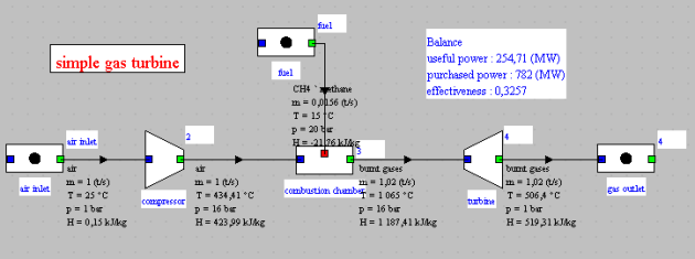
It is a very simple cycle, the synoptic view of which is given below:
The diagram and project files are given below. Please note that they require the use of Thermoptim in English, i.e. with the inth2.zip file of this language.
Raw Generated Equations
There are 42 of them. They are given in this file.
Redundancies
The redundancies identified are as follows:
Redundancy for m_dot_gasoutlet:
# 1 m_dot_gasoutlet = m_dot_turbine, equation: 1
# 2 m_dot_gasoutlet = 1.01827, equation: 2
Redundancy for m_dot_fuel:
# 1 m_dot_fuel = 0.015643905, equation: 3
# 2 m_dot_fuel = abs(Q_dot_combustionchamber/DeltaHr_combustionchamber), equation: 34
Redundancy for m_dot_compressor:
# 1 m_dot_compressor = m_dot_airinlet, equation: 8
# 2 m_dot_compressor = m_dot_airinlet, equation: 9
These redundancies relate to flow rates and are easy to resolve. The equations to keep are 1, 34 and 8, with 9 being a duplicate.
Uninitialized Variables
Il n'y a pas de variable non initialisée
List of Equation Groups
Group 1
Group 1 (13 Variables) : [T_fuel, p_2, p_4, T_3, p_fuel, m_dot_fuel, etaT_turbine, a_combustionchamber, p_airinlet, T_airinlet, m_dot_gasoutlet, m_dot_airinlet, etaT_compressor]
Group 1 (Equations):
m_dot_gasoutlet = 1.01827
m_dot_fuel = 0.015643905
m_dot_airinlet = 1.0
T_airinlet = 25.0
p_airinlet = 1.0
etaT_compressor = 0.85
p_2 = 16.0
etaT_turbine = 0.85
p_4 = 1.0
T_3 = 1065.0
a_combustionchamber = 4
T_fuel = 15.0
p_fuel = 20.0
We find here all the equations providing the data for the problem, except T_3 identified as missing.
Group 2
Group 2 (5 Variables) : [DeltaHr_combustionchamber, p_3, h_airinlet, m_dot_compressor, h_fuel]
Group 2 (Equations):
h_airinlet = calcH_TP("air";T = T_airinlet ;P = p_airinlet)
m_dot_compressor = m_dot_airinlet
m_dot_compressor = m_dot_airinlet
DeltaHr_combustionchamber = (-(-74850) +(-393520)+a_combustionchamber/2*(-242000))/16
p_3 = p_2
h_fuel = calcH_TP("CH4 ` methane";T = T_fuel ;P = p_fuel)
This second group corresponds to equations that allow the calculation of new variables through simple substitution of those from the first group.
Group 3
Group 3 (2 Variables) : [s_airinlet, m_dot_combustionchamber]
Group 3 (Equations):
s_airinlet = calcS_PH("air";P = p_airinlet;H = h_airinlet)
m_dot_combustionchamber = m_dot_compressor + m_dot_fuel
This third group corresponds to equations that allow the calculation of new variables through simple substitution of those from the first and second groups.
The process is repeated in the subsequent groups.
Unresolved Equations
There are no unresolved equations.
These are the equations that either depend on the properties of the fluid or cannot be directly solved.
Conversion to EES format
EES is a solver developed by f-Chart, which requires a license. The conversion results in a file that can be processed by the solver. The equations for calculating the fluid properties converted to this format are given below, the others remaining unchanged:
//Equation: 7
h_airinlet = enthalpy(air;T = T_airinlet) // Downstream point - air inlet
s_airinlet = entropy(air;P = p_airinlet;H = h_airinlet) // Upstream point - air inlet - Downstream point - 2
//Equation: 11
hs_2 = enthalpy(air;P = p_2;S = s_airinlet) // Downstream point - 2
//Equation: 14
T_2 = temperature(air;H = h_2) // Downstream point - 2
//Equation: 18
s_3 = entropy(burnt gases;P = p_3;H = h_3) // Upstream point - 3 - Downstream point - 4
//Equation: 19
hs_4 = enthalpy(burnt gases;P = p_4;S = s_3) // Downstream point - 4
//Equation: 21
h_4 = h_3 - etaT_turbine*(h_3 - hs_4) // Upstream point - 3 - Downstream point - 4
//Equation: 22
T_4 = temperature(burnt gases;H = h_4) // Downstream point - 4
//Equation: 23
s_4 = entropy(burnt gases;P = p_4;H = h_4) // Entropy
//Equation: 28
lambda_combustionchamber = LAMBD(T_2;T_3;a_combustionchamber)// air factor lambda
//Equation: 29
h_3 = h_products(T_3;a_combustionchamber;lambda_combustionchamber)// enthalpy of the reactants
//Equation: 30
hfict_2 = h_products(T_2;a_combustionchamber;lambda_combustionchamber)// enthalpy of a fictitious inlet point for calculating the heat released
//Equation: 38
h_fuel = enthalpy(CH4 ` methane;T = T_fuel) // Fuel point – fuel
As explained in the section "Calculations Downstream of a Combustion Chamber," all equations concerning the properties of the 'burnt gases' substance must be adapted to use the two calculation functions defined at the beginning of the generated file. In equation 38, the substance must be renamed simply to CH4.
It should be noted that EES uses the decimal separator defined in the Windows regional settings, which is '.' in the United States and ',' in Europe. Similarly, in function arguments, ',' is used in the United States and ';' in Europe. It may therefore be necessary to replace these separators according to the Windows settings.
The file that can be resolved in EES is provided below.
Other examples not commented
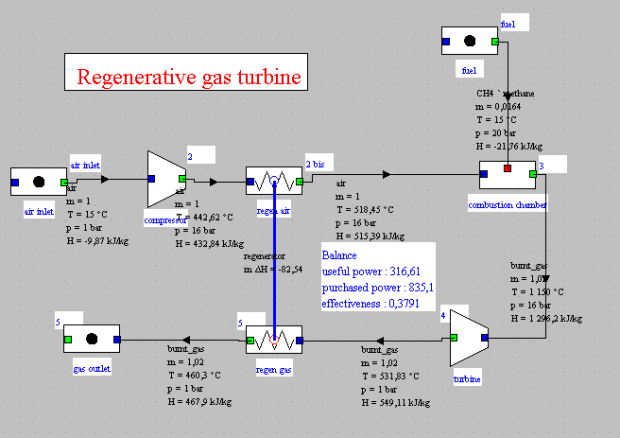
Regenerative gas turbine

Raw Equations File
Executable file in EES
High-temperature nuclear power plant with intermediate heat exchanger
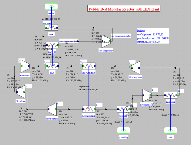
This is a helium Brayton cycle envisaged for high-temperature nuclear reactors (900 °C) of about a hundred MWe, using low-enriched uranium pebbles coated in carbon (which acts as a moderator) and using helium as a heat transfer fluid. It is a variant of the cycle presentedthe in guided exploration CTRN-5.
Its synoptic view is given below:
File of the104 raw equations
Executable file in EES (117 equations)


